Introduction to Etching Compensation
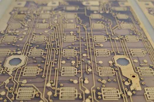
One critical step in the PCB manufacturing process is etching, where unwanted copper is removed to form the desired circuit patterns. However, during etching, factors such as chemical reactions and process variations can cause deviations from the intended design. This is where etching compensation comes into play.
Etching compensation involves adjusting the dimensions of the artwork to account for material removal during the etching process. By pre-emptively altering the trace widths and spacing on the design files, manufacturers can ensure the final product closely matches the intended specifications. This compensation is crucial for maintaining the electrical performance and reliability of the PCB.
The importance of etching compensation cannot be overstated. Precise control over the trace widths and spacing is essential for achieving the desired electrical characteristics, such as impedance and signal integrity. Without proper compensation, the etched traces could end up too narrow or too wide, leading to potential failures in the electronic device.
In this blog, we will explore why etching compensation is necessary, its impact on impedance, the relevant IPC standards, how manufacturers handle compensation for high-speed PCB and high-frequency PCB, and best practices to achieve optimal results.
Why Etching Compensation is Necessary from a PCB Manufacturing Perspective
The etching process involves several steps, including coating the PCB with a photoresist, exposing it to a pattern, developing the exposed resist, and finally etching away the unprotected copper. Despite advancements in manufacturing technology, the etching process is still subject to various factors that can affect the precision of the trace widths and spacing. These factors include:
- Chemical concentration: Variations in the concentration of the etching solution can lead to uneven material removal.
- Temperature fluctuations: Changes in temperature can affect the rate of chemical reactions, causing inconsistencies in etching.
- Process duration: The time the PCB is exposed to the etching solution can impact the amount of copper removed.
- Equipment calibration: Inaccuracies in the calibration of etching equipment can lead to deviations from the desired dimensions.
These challenges make it difficult to achieve the precise trace widths required for modern PCBs. Without etching compensation, the final traces may be too thin, leading to increased resistance, reduced current-carrying capacity, and potential overheating. Conversely, traces that are too wide can result in crosstalk, signal interference, and compromised circuit performance.
Etching compensation addresses these issues by adjusting the original artwork to account for the expected material removal. By doing so, manufacturers can produce PCBs that meet the stringent requirements of electronic devices, ensuring reliable operation and long-term durability.
Will Etching Compensation Affect Impedance Output?
Impedance is a critical parameter in PCB design, especially for high-frequency and high-speed applications. It refers to the resistance to the flow of alternating current (AC) in a circuit and is influenced by the trace width, trace thickness, and the dielectric properties of the PCB material. Maintaining the correct impedance control is essential for signal integrity and minimizing signal loss.
Etching compensation directly impacts impedance because it alters the trace widths. If the compensation is not done correctly, the resulting traces may not match the intended impedance, leading to signal integrity issues. For instance, if the traces are narrower than designed, the impedance will be higher, causing signal reflections and potential data errors. Conversely, wider traces result in lower impedance, which can also degrade signal quality.
Manufacturers address this by carefully calculating the amount of compensation needed to achieve the desired impedance. This involves:
- Pre-compensation calculations: Determining the expected material removal and adjusting the trace widths accordingly.
- Test coupons: Creating test structures on the PCB that can be measured to verify the actual impedance after etching.
- Iterative adjustments: Fine-tuning the compensation parameters based on the test results to ensure the final traces meet the impedance requirements.
By implementing these strategies, PCB manufacturers can ensure that etching compensation does not adversely affect impedance, maintaining the signal integrity and performance of the PCB.
IPC Etching Tolerance from Original Artwork
The IPC sets the standards for PCB design and manufacturing to ensure consistency, reliability, and quality across the industry. One such standard is IPC-6012, which specifies the performance and qualification requirements for rigid PCBs. Within this standard, there are guidelines for etching tolerance, which refer to the allowable deviations from the original artwork dimensions.
According to IPC-6012, the etching tolerance typically ranges from ±10% to ±20% of the trace width. This means that if a trace is designed to be 10 mils wide, the actual width after etching should be within 9 to 11 mils for a ±10% tolerance. Adhering to these standards is crucial for ensuring that the PCB meets the design specifications and performs as intended.
Manufacturers use these standards as a benchmark for their etching processes. By following the IPC guidelines, they can produce PCBs that are consistent in quality and performance, reducing the risk of failures and ensuring customer satisfaction.
How Factories Control Their Etching Compensation for High-Speed or High-Frequency PCBs
High-speed and high-frequency PCBs present unique challenges for etching compensation. These PCBs require tighter control over trace widths and spacing to maintain signal integrity and minimize losses. Factories employ several techniques to achieve the necessary precision:
- Advanced photolithography: Using high-resolution photomasks and precise exposure equipment to create accurate patterns on the PCB.
- Automated process control: Implementing automated systems to monitor and adjust the etching process in real-time, ensuring consistent results.
- Regular calibration: Frequently calibrating equipment to maintain accuracy and prevent deviations from the desired dimensions.
- Statistical process control (SPC): Using statistical methods to analyze process data and identify trends or anomalies, allowing for proactive adjustments.
By leveraging these techniques, manufacturers can effectively control etching compensation for high-speed and high-frequency PCBs, ensuring that the final products meet the stringent performance requirements of modern electronic devices.
Best Practices for Etching Compensation
Achieving optimal results in etching compensation requires collaboration between PCB designers and manufacturers. Here are some best practices to consider:
- Design for manufacturability (DFM): Incorporate etching compensation into the design phase, considering the manufacturing capabilities and limitations.
- Use of simulation tools: Utilize software tools to simulate the etching process and predict the necessary compensation adjustments.
- Regular communication: Maintain open lines of communication between designers and manufacturers to address any issues or changes in the design or process.
- Continuous improvement: Implement a feedback loop to review the performance of the etching process and make continuous improvements.
By following these best practices, both designers and manufacturers can ensure that etching compensation is effectively implemented, resulting in high-quality PCBs that meet the demands of modern electronic devices.
